High Performance Circuit Board Projects - Custom high quality cost-effective Rigid-Flex Printed Circuit Boards Making – PCBShinTech
High Performance Circuit Board Projects - Custom high quality cost-effective Rigid-Flex Printed Circuit Boards Making – PCBShinTech Detail:
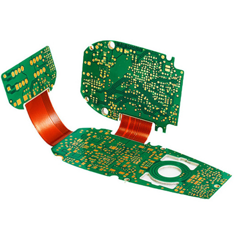
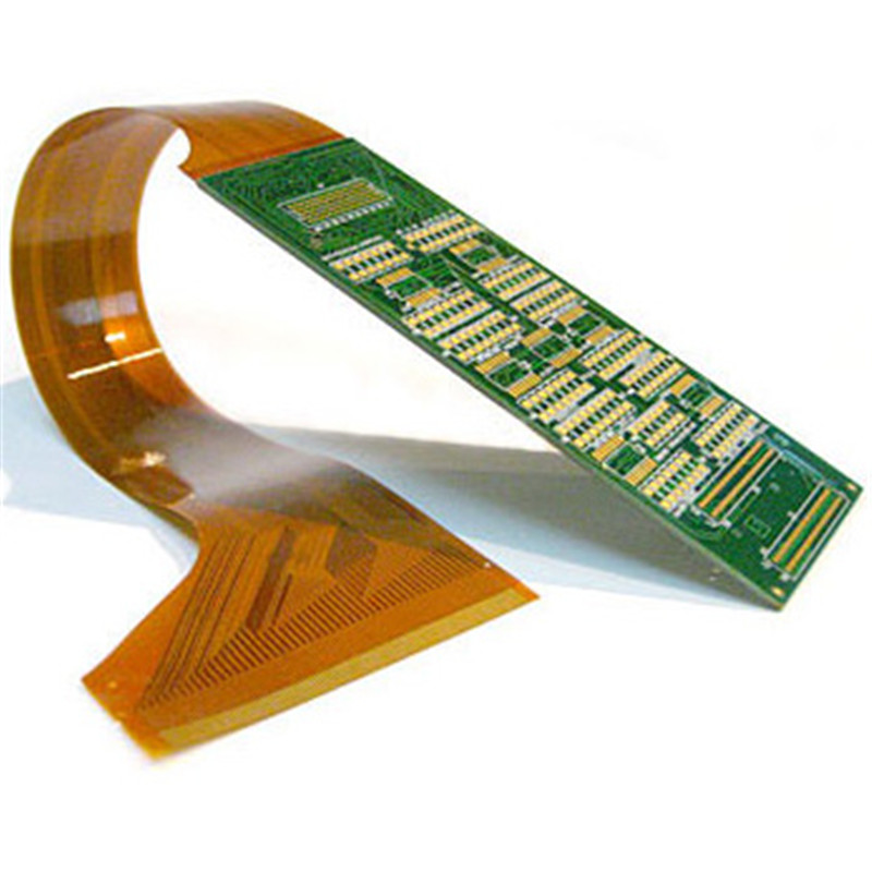
As the name implies, rigid-flex PCBs are the composition of rigid circuit boards and flexible circuit boards that are permanently connected to one another. Rigid-flex are a type of high-adaptability PCBs that use both flexible and rigid-board construction in an application.
Due to the advantages that Rigid-Flex circuit boards have, they are used in an even wider range of applications including:
● Consumer electronics
● Contract manufacturing
● High-speed digital development
● Instrumentation
● LEDs and lighting
● Power electronics
● RF and microwave equipment
● And other industrial applications
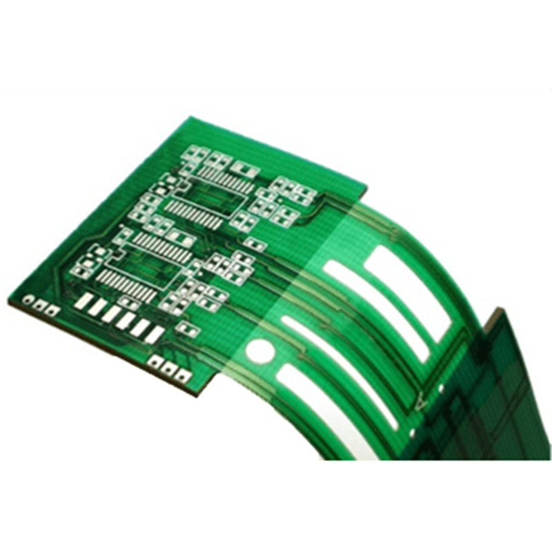
The proper application of Rigid-Flex circuit boards offers optimum solutions for difficult, limited space conditions. This technology offers the possibility of a secure connection of device components with the assurance of polarity and contact stability, as well as a reduction in plug and connector components. Additional advantages of Rigid-Flex circuit boards are dynamic and mechanical stability, the resulting 3-dimensional freedom of design, simplified installation, space savings, and maintenance of uniform electrical characteristics. Use of Rigid-Flex circuit boards can reduce the total cost of the final product.
Though they offer greater spatial efficiency and cost, weight savings, rigid-flex PCBs require different design rules and can be more challenging than rigid boards both for designer and manufacturers. PCB ShinTech is experienced with helping many of our customers bring their complex rigid-flex printed circuit boards design to market.
Save yourself time and safeguard your budget when you contact PCB ShinTech today to discuss your upcoming project. You’ll experience, rapid quote response, flexible lead times, technical support, and price-to-value for rigid-flex solutions. Contact Us»
A standardized manufacturing process following IPC guidelines guarantees a reliable and simultaneously an economical product, which is ISO9001, TS16949 and UL certified.
Click here to Inquiry or Get a Quote
Technical options for Rigid-Flex PCBs
Most rigid-flex circuits are multi-layered. A rigid-flex PCB can include one/several flex boards and rigid boards, which are connected through internally/externally plated-through holes.
Check the PCB ShinTech manufacturing capabilities of the rigid-flex PCB.
|
|
Options |
|
Layers |
2 to 24 layers, including “flying tails” |
|
Conductor width min. |
75µm |
|
Annular ring min. |
100µm/4mil |
|
Via min. Ø |
0.1mm |
|
Surfaces |
Chemical gold (recommended), immersion tin, HAL lead-free |
|
Materials |
Flex (Polyimide, high Tg polyimide) +Rigid (FR-4, FR-4 high Tg, Aluminum, Teflon, others) |
|
Material thickness |
Polyimide starting at 62µm doublesided, FR4 starting at 100µm |
|
Max. size |
250mm x 450mm |
|
Solder-stop |
Coverlay or flexible solder-stop |
|
Quality Grade |
IPC Class II, IPC Class III |
|
Special Specification |
Half-cut/Castellated Holes, Impendence Control, Layer Stackup |
Flexible Part of the Rigid-Flex PCB
|
|
Options |
Inclusive |
|
Layer |
1 to 10 layers, plated-through |
- |
|
Annular ring min. |
100µm |
100µm |
|
Via min. Ø |
0.15mm |
0.2mm |
|
Surfaces |
Chemical gold (recommended),ENEPIG, chem silver |
Chemical gold |
|
Materials |
Polyimide, high Tg polyimide |
Polyimide |
|
Copper thickness |
from 18µm/ 0.5 oz |
18µm, 35µm |
|
Stiffener |
0.025µm – 3.20mm |
0.2mm, 0.3mm |
|
Max. size |
250mm x 450mm |
- |
|
Impedance control |
Yes (10% tolerance) |
- |
|
Tests |
E-Test |
Please refer to the Full PCB manufacturing Capabilities Sheet ».
Layout Recommendations for Rigid-Flex PCBs
|
Circuit Construction |
Bend Radius Calculation |
|
1 Layer (single-sided) |
Flex Thickness x 6 |
|
2 Layer (double-sided) |
Flex Thickness x 12 |
|
Multi-Layer |
Flex Thickness x 24 |
Other Design Tips Include:
● Avoid 90˚ bends whenever possible.
● Gradual bends are always safer.
● Bend radius is measured from the inside of the bend.
● Conductors running through a bend need to be perpendicular to the bend.
● Use curved traces instead of traces with corners.
● Traces should be perpendicular to your bend.
Send your enquiry or quote request to us at sales@pcbshintech.com to get connected to one of our sales representatives who have the industry experience to help you get your idea to market.
Product detail pictures:


Related Product Guide:
We enjoy an extremely good status among our prospects for our great merchandise top quality, competitive price and the ideal service for High Performance Circuit Board Projects - Custom high quality cost-effective Rigid-Flex Printed Circuit Boards Making – PCBShinTech , The product will supply to all over the world, such as: Nepal, Berlin, Ecuador, Further, we are supported by highly experienced and knowledgeable professionals, who have immense expertise in their respective domain. These professionals work in close coordination with each other to offer our clients an effective range of products.
Hope that the company could stick to the enterprise spirit of "Quality, Efficiency, Innovation and Integrity", it will be better and better in the future.


